How to wire a Wall Power Meter
BLOGS
6/11/20223 min read
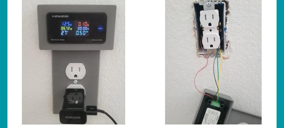
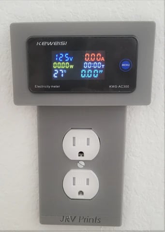
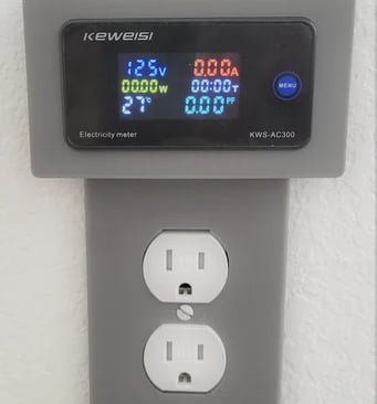
This post provides guidance to help you wire your JRV Wall Power Meter for 125VAC 60hz, 15A circuits. This product was designed to easily replace your existing US standard 1-gang faceplate with a compact faceplate that integrates a power meter display.
JRV has two faceplate models; one for decorator/rocker plates typically used for GFCI receptacles (square in shape), one for duplex outlets receptacles (plate has two outlet holes). No modification is needed to your existing receptacle wiring, you just add a few low-power cables to power supply the display, and its hall sensor. The JRV Power Meter features a bright color LCD display with no dead angle, and shows key electrical data including, Volts, Watts, KWH, Amps, Cumulative Time, and Temperature.
Required Parts:
1x Keweisi Digital Meter Display (KWS AC300) - Amazon Link
1x JRV Wall Power Meter for Standard Duplex Outlets (from jrvprints) - Link
or
1x JRV Wall Power Meter for GFCI Outlets (from jrvprints) - Link
2x Low-power wires to power supply the display. 4-5 inches long, 30-33 Wire Gauge (AWG).
Disclaimer: this page includes affiliate links. If you click and purchase, JRV prints may receive a small commission at no extra cost to you.
Connecting Hall Sensor
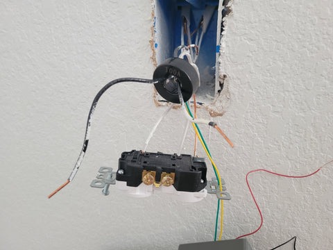
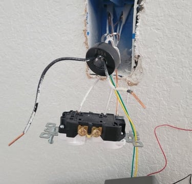
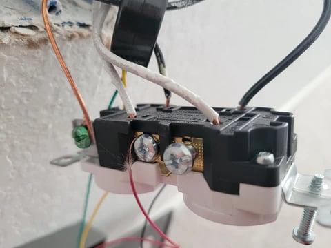
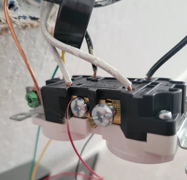
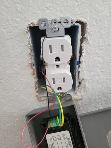
- You will need to detach both hot lines from the receptacle to install the display hall sensor (current sensor - circle in shape), see picture 2.
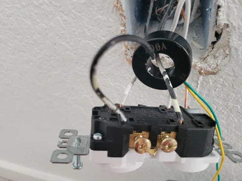
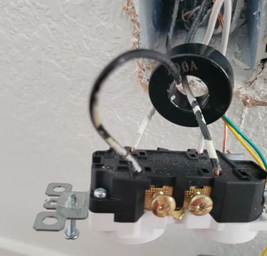
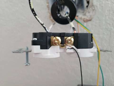
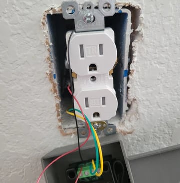
- Re-attach the hot lines keeping your original receptacle wiring, see picture 3. Watch this video if you need help understanding how to use push model receptacles.
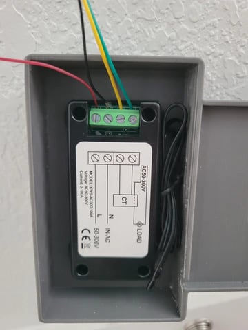
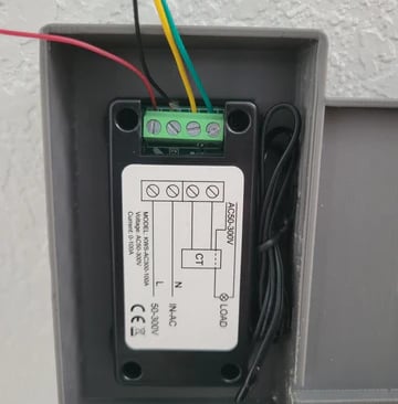
- Finally connect the halls sensor's yellow and green cables to the display's CT terminals. See picture 6.
Connecting Temperature Sensor
- Connect the two-pin temperature terminal connector as shown in picture 6. The temperature terminal receptacle is located at the bottom side of the display. Note: you can place the temperature sensor anywhere. For example, outside the box to get ambient temperature, or inside attached to get cables' temperature. You don't need to connect the temperature sensor necessarily; the device will operate normally.
Connecting Display Power Supply
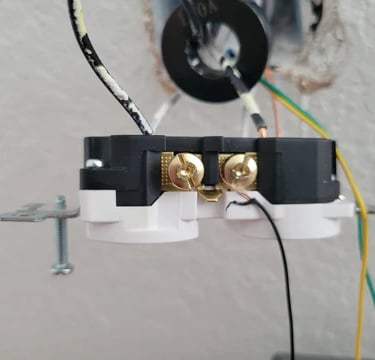
- Provide 125 VAC to the display meter by connecting the red, and black wires to each hot line as shown in the picture 4, 5.
- Connect these two wires to the displays' N, L terminals (In-AC). See picture 6.
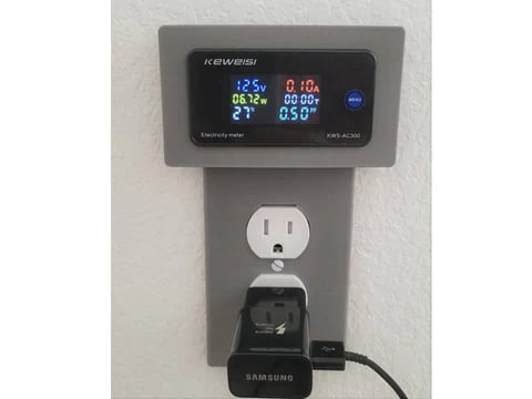
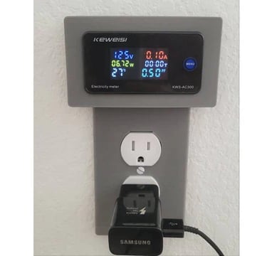
- Finally screw the receptacle in place, and then JRV Wallplate. Reconnect your power breaker and test your connections by checking the voltage output of the receptacle. You should expect the display always on, showing 0's and the current temp if nothing is connected.
THIS IS NOT ELECTRICAL ADVICE. Please hire your local professional electrician.
JRV Wall Power Meter is a prototype for non-production purposes.
Questions, ideas contact us
JDV Design
Colorado, USA